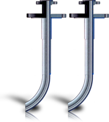
Dip Pipes and Spargers
Ethylarmor is a PTFE lined and covered armored dip pipe or sparger designed exclusively for the rigorous demands of agitating vessels or the high stress of injection. Also available is Ethylene's Solid PTFE dip pipes and spargers for non-agitated services.
Ethylarmor® High Temperature Corrosion Resistance
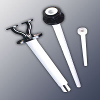
Ethylene Ethylarmor Dip Tubes and Spargers combine the high temperature and near-universal corrosion resistance of PTFE with the mechanical strength of an encapsulated Schedule 80 carbon steel pipe for tough applications such as agitated reactors.
Ethylarmor® Durability
Ethylarmor Dip Tubes and Spargers pass both the ASTM F423 steam-cold water cycle test and a 10,000 volt electrostatic spark test, the industry's most rigorous testing program. This virtually eliminates the possibility of heat-seal failure and resultant damage to the reactor's fragile glass lining.
Ethylarmor® Design
A broad range of optional features are available to meet your process requirements. These include Diverters (to direct liquid/gas flow away or towards vessel walls), Extended Flares (to eliminate additional reducing flanges), Sparger, Anti-Siphon Holes, etc.
Ethylarmor® Extended Flare Technology
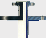
Extended Flare Technology
Ethylene's Extended Flare Face technology eliminates costly reducing flanges by allowing oversized mounting flanges to be integrated into dip tube fabrication. This is also an important factor in the reduction of fugitive emissions; fewer connections mean fewer leak points. The extended flare is subjected to the same rigorous steam-cold water and a 10,000 voltage test as other Ethylarmor products.
Ethylarmor® Nozzle Liners
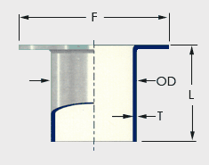
Nozzle Liners
Used in glass-lined steel reactors and vessels, Ethylene nozzle liners eliminate damage to fragile nozzles during the insertion and operation of dip tubes, Spargers and instrumentation. Nozzle liners also reduce erosion of the glass or alloy vessel nozzles by steam or abrasive materials, preventing process contamination and expensive repairs. Solids build-up is also reduced. They are provided in lengths to meet your exact requirements.
| Nozzle Liner Dimensions | ||||||||
|---|---|---|---|---|---|---|---|---|
| Diameters through 36" are available. Please consult the factory for diameters over 14" not listed. Note: Nominal dimensions shown. | ||||||||
| Nozzle Size |
OD | Flare F |
Wall T |
Nozzle Size |
OD | Flare F |
Wall T |
|
| 1/2 | 1/2 | 1-3/8 | 1/16 | 4 | 3-13/16 | 6-3/16 | 1/8 | |
| 3/4 | 3/4 | 1-11/16 | 1/16 | 6 | 5-3/4 | 8-1/2 | 1/8 | |
| 1 | 15/16 | 2 | 1/16 | 8 | 7-3/4 | 10-5/8 | 1/8 | |
| 1-1/2 | 1-7/16 | 2-7/8 | 1/16 | 10 | 9-3/4 | 12-3/4 | 5/32 | |
| 2 | 1-15/16 | 3-5/8 | 1/16 | 12 | 11-3/4 | 15 | 5/32 | |
| 3 | 2-15/16 | 5 | 1/8 | 14 | 13-3/4 | 16-1/4 | 5/32 | |
Ethylarmor® Diverter Tube
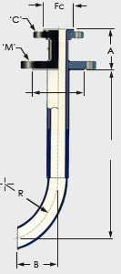
Diverter Tube
A unique tight radius bend capability is ideal when a diverter is required to deflect liquid or gas either toward or away from a vessel wall. The curvature at the bottom of the tube simplifies the installation of the dip tube in reactors with limited overhead space. Variations of the standard diverter's geometry can be accommodated in most cases. Please contact the factory for assistance.
| Diverter Data | |||||
|---|---|---|---|---|---|
| All Dimensions in inches. See table below for connection and Mounting Flange Data. | |||||
| Nominal Size |
B (Nom.) |
R (Nom.) |
A (Nom.) |
Max OD |
L (Nom.) |
| 1 | 4" | 6" | 5" | 1-5/8 | 18" |
| 1-1/2 | 5" | 8" | 5" | 2-1/4 | 21" |
| 2 | 6" | 10" | 5" | 2-13/16 | 27" |
| 3 | 6" | 16" | 5" | 3-15/16 | 30" |
| 4 | 8" | 20" | 6" | 4-15/16 | 36" |

Highlights
- A variety of diameters and length configurations
- Withstand the heat, corrosion, and stress of your most demanding process
- Pass both the ASTM F423 steam-cold water cycle test and a 10,000 volt electrostatic spark test, the industry's most rigorous testing program
- A broad range of optional features are available to meet your process requirements
Color Legend
- Carbon Steel
- PTFE
Special Orders
Ethylene prides itself on its ability to respond to customer needs. Please contact the factory for information on items not shown on our website.
Ethylarmor® DF and SF Dip Tubes
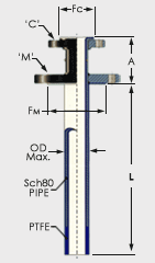
DF Dip Tube
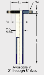
SF Dip Tube
These standard dip tubes can be supplied in a variety of diameters and length configurations. Maximum recommended unsupported length for agitated service is shown in the table below (a general guide only). Ethylene will review your specific service conditions and advise a suitable dip tube construction.
| Ethylarmor SF and DF Dip Tube Data | ||||||||||
|---|---|---|---|---|---|---|---|---|---|---|
| All Dimensions in inches *Denotes size Mounting Flanges available on SF type dip tubes. |
||||||||||
| Nominal Size |
PTFE Wall |
Connecting Flange |
Mounting Flange |
PTFE Flare | A | T | Max. |
Max. |
Max. Unsupported Length for Agitation |
|
| 'C' | 'M' | FC | FM | OD | L | |||||
| 3/4 | .090 | 3/4 | 1-1/2 | 1-11/16 | 2-7/8 | 5 | - | 1-3/8 | 20'-0" | 3'-0" |
| 1 | .090 | 1 | 2 | 2 | 3-7/8 | 5 | - | 1-5/8 | 20'-0" | 3'-6" |
| 1-1/2 | .125 | 1-1/2 | 3 4 6 8 |
2-7/8 | 5 6-3/16 8-1/2 10-5/8 |
5 | - | 2-1/4 2-9/16 |
20'-0" | 5'-0" |
| 2 | .125 | 2 | 3* 4 6 8 |
3-5/8 | 5 6-3/16 8-1/2 10-5/8 |
5 | 1 | 2-13/16 3 |
20'-0" | 6'-0" |
| 3 | .125 | 3 | 4* 6 8 |
5 | 6-3/16 8-1/2 10-5/8 |
5 | 1-3/16 | 3-15/16 4-1/8 |
15'-0" | 8'-0" |
| 4 | .150 | 4 | 6* 8 |
6-3/16 | 8-1/2 10-5/8 |
6 | 1-1/4 | 4-15/16 5-1/4 |
15'-0" | 10'-0" |
| 6 | .150 | 6 | 8 | 8-1/2 | 10-5/8 | 6 | 1-3/8 | 7-1/16 | 10'-0" | 10'-0" |
| 8 | .170 | 8 | 10 | 10-5/8 | 12-3/4 | 6 | 1-9/16 | 9-3/16 | 9'-6" | 9'-6" |
Ethylarmor® AGI Dip Tube
for Severe Agitation Service.
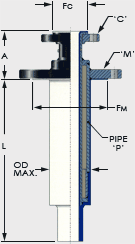
AGI Dip Tube
The AGI Dip Tube is intended for use in services where the combination of length and loading prohibit the use of standard Ethylarmor DF Dip Tubes. The larger outer diameter reinforcing pipe significantly increases the ability of the dip tube to withstand external loading. Severe agitation applications of smaller diameter Ethylarmor dip tubes my require additional reinforcement of the dip tube. Ethylene can offer Schedule 120 or even Schedule 160 reinforcing pipe for special applications.
| Ethylarmor AGI Dip Tube Data | ||||||||
|---|---|---|---|---|---|---|---|---|
| All Dimensions in inches | ||||||||
| Nominal Size |
Connecting Flange |
Mounting Flange |
Reinforcing Pipe |
PTFE Flare | A | Max. |
Max. Entry Length |
|
| 'C' | 'M' | 'P' | FC | FM | OD | L | ||
| 1 | 1" | 4" 6" 8" |
3" | 2 | 6-3/16” 8-1/2” 10-1/2” |
5" | 3 15/16" 4 1/4" 4 1/4" |
15'-0" |
| 1-1/2 | 1-1/2" | 4" 6" 8" |
3" | 2-7/8 | 6-3/16” 8-1/2” 10-1/2” |
5" | 3 15/16" 4 1/4" 4 1/4" |
15'-0" |
| 1-1/2 | 1-1/2" | 6" 8" |
4" | 2-7/8 | 8-1/2” 10-1/2” |
6" | 4 15/16" 5 3/8" |
15'-0" |
| 2 | 2" | 6" 8" |
4" | 3-5/8 | 8-1/2” 10-1/2” |
6" | 4 15/16" 5 3/8" |
15'-0" |
Ethylarmor® Solid PTFE Dip Tubes
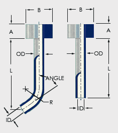
Solid Dip Tubes, Diverters, and Spargers
Ethylene's solid PTFE Dip Tubes are fabricated from heavy-walled virgin PTFE tubes. All flanges are threaded onto the tube and pinned in place.
Consult Ethylene for applications involving nonstandard sizes or multiple bend configurations. The table below gives dimensions.
| Solid Dip Tube Dimensions | ||||||
|---|---|---|---|---|---|---|
| All Dimensions in inches | ||||||
| Nominal Dia. |
Nozzle Size |
OD | ID | A | B | R |
| 1/2 | 1 | 1 | 1/2 | 1 | 2 | 4 |
| 1 | 1-1/2 | 1-3/8 | 7/8 | 1-1/2 | 2-7/8 | 6 |
| 1-1/2 | 2 | 1-7/8 | 1-1/8 | 1-3/4 | 3-5/8 | 8 |
| 2 | 3 | 2-3/4 | 2 | 2 | 5 | 10 |
| 3 | 4 | 3-1/2 | 2-1/2 | 2-3/4 | 6-1/4 | 16 |
| 4 | 6 | 4 | 3 | 3 | 8-1/2 | 20 |
Color Legend
- Carbon Steel
- PTFE
Special Orders
Ethylene prides itself on its ability to respond to customer needs. Please contact the factory for information on items not shown on our website.
Ethylarmor® Spargers
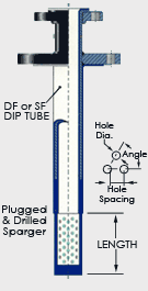
DF Sparger
Ethylarmor Spargers are ideal for steam entrainment or other applications where diffusion of the process fluid is desired. The bottom section of the sparger is an integral part of the encapsulating PTFE liner. It is designed to provide a radial spray that can be tailored to your exact requirements. Spargers can be drilled to your specifications: number and diameter of holes, distance from the end of the tube, and length of drilled section can all be specified.
| Sparger Dimensions | |||||
|---|---|---|---|---|---|
| All Dimensions in inches | |||||
| Nominal Size |
Length | Hole Number |
Hole Diameter |
Hole Spacing |
Angle |
| 1 | 6 | 16 | 1/4" | 1.02 | 60° |
| 1-1/2 | 6 | 16 | 3/8" | 1.47 | 60° |
| 2 | 6 | 32 | 3/8" | 1.25 | 60° |
| 3 | 8 | 40 | 1/2" | 1.38 | 60° |
| 4 | 10 | 64 | 1/2" | 1.77 | 60° |
Ethylarmor® Solid PTFE Spargers
Ethylene solid PTFE Spargers are fabricated from heavy-walled virgin PTFE tubes. All flanges are threaded onto the tube and pinned in place. Spargers are drilled to your specifications; number and diameter of holes, distance from the end of the tube and length of drilled section.
Color Legend
- Carbon Steel
- PTFE
Special Orders
Ethylene prides itself on its ability to respond to customer needs. Please contact the factory for information on items not shown on our website.
Ethylarmor® Calculations
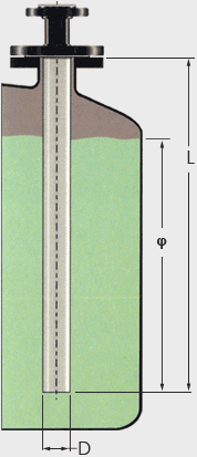
Dip Tube Calculation
Dip Tubes and spargers used in agitated service are subject to loads which under certain conditions can be so great that bending or complete failure of the unit can occur. Therefore, it is important that these loads be considered when designing or specifying a dip tube or sparger for use in highly agitated service with highly viscous materials.
To determine these loads, the following must be known:
- V – Velocity of the process fluid past the tip of the dip tube (ft/sec)
- D – Outside diameter of the dip tube (ft) See table
- L – Entry Length of the dip tube (ft)
- φ – Length of the dip tube immersed in fluid (ft)
- µ – Dynamic viscosity of the process fluid (lbs sec/ft2)
- ρ – Mass density of the process fluid (slugs/ft3) [(1slug/ft3 =32.17lb/ft3)]
Note: These equations are provided as a guide only and do not constitute a warrarnty, expressed or implied, for the fitness of an Ethylarmor® Dip Tube in specific service
The total force exerted on the tube, F, can be determined from the above information. FT is the resultant of the drag and lift forces acting on the tube, FD and FL respectively. FT is given by Equation 1.
Equation 1
FT = √FD2 + FL2
The viscous drag force, FD, is defined by Equation 2.
Equation 2
- when: A = φ D
- FD = CD V2 ? A
2
the lift force FL, created by alternate vortex shedding on the back surface of the immersed tube is given by Equation 3.
Equation 3
FL = CL ρ V2 A
2
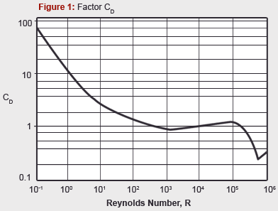
The coefficients for lift and drag, CD and CL, are based on the Reynolds number which can be calculated using Equation 4.
Equation 4
- Reynolds Number,
- R = ρ D V
µ
CD can be gotten from Figure 1 shown below.
- CL is as follows:
- CL = 0.8
- CL = 2.4 – 0.4Log10R
- CL = 0.4
- when:
- (R < 105)
- (105 < R < 106)
- (R > 106)
| Factors WD, H and D | |||
|---|---|---|---|
| Nominal Size |
WD | H | D |
| 3/4 | 1,877 | 11.75 | 0.101 |
| 1 | 3,533 | 18.79 | 0.123 |
| 1-1/2 | 9,064 | 41.62 | 0.179 |
| 2 | 16,080 | 66.79 | 0.219 |
| 3 | 48,970 | 147.02 | 0.312 |
| 4 | 93.940 | 247.88 | 0.401 |
| 6 | 187,000 | 573.19 | 0.583 |
| 8 | 369,820 | 981.23 | 0.760 |
Equation 1 can be rewritten as:
Equation 5
FT = ρ V2 A√CD2 + CL2
2
The value obtained by Equation 5 must be less than or equal to the maximum allowable load recommended by Ethylene Corporation for the selected unit. The maximum load, Sm, for dip tube or sparger is given by Equation 6:
Equation 6
Sm =WD
12(L -0.5φ)
where WD is the factor given in table If FT < Sm, the unit is sufficiently strong for the intended service. However, a check for resonance should be made.
If the natural frequency of the dip tube is too close to the wake frequency, resonance can occur in the dip tube causing stresses much greater than expected. The natural and wake frequency must be calculated and the ratio of these frequencies must be greater than v2 or less than 0.5.
The natural frequency of the dip tube can be calculated using Equation 7 where the value of factor H is taken from table.
Equation 7
Wn = 135 √H/L4
The wake frequency, W, is calculated using Equation 8.
Equation 8
W = 0.22 V
D
The ratio W/Wn should be less than 0.5 or greater than √2
-
Example 1: Dip Tube is Adequate
V, fluid velocity = 15 (ft/sec) Dip tube size = 3” or 0.312 (ft) from the table L, entry length = 80” or 6.67 (ft) φ, immersed length = 65” or 5.52 (ft) µ, dynamic viscosity = 1.10 centipoise or 2.298x10⁻⁵ 1lbs sec/ft2 ρ, fluid mass density = 2.10 slugs/ft3 Step 1:
Determine Reynolds number,
R = (2.10• 0.312• 15)/2.298x10-5 =4.277x10⁵Step 2:
Determine CD and CL
CD = 0.90(Fig.1), CL = 2.4 – 0.4Log10R (4.277x10⁵)=0.148Step 3:
Calculate Force FT using Equation 5,
FT = 0.5• 2.10• 152• (.312• 5.42) x √0.92• 0.1482 = 364lbsStep 4:
Calculate allowable force, Sm using Equation 6,
Sm = 48,970/(12•6.67-0.5•5.41)) = 1,030 lbs
Since 364 < 1,030 a 3” dip tube would be adequate for this application.Step 5:
Determine the natural frequency, Wn, of the dip tube from Equation 7,
Wn = 135v147.024/6.674 = 36.8 HzStep 6:
Determine wake frequency, W, using Equation 8,
WD = 0.22• 15 / 0.312 = 10.6 HzStep 7:
Test ratio of W / Wn = 10.6 / 36.8 = 0.29
Since 0.29 < 0.5, the dip tube passes the test -
Example 2: Dip Tube is Inadequate
V, fluid velocity = 15 (ft/sec) Dip tube size = 1-1/2 or 0.179 (ft) from table L, entry length = 80” or 6.67 (ft) φ, immersed length = 65” or 5.42 (ft) µ, dynamic viscosity = 1.10 centipoise or 2.298x10⁻⁵ sec/ft2 ρ, fluid mass density = 2.10 slugs/ft3 Step 1:
Determine Reynolds number,
R=(2.10• 0.179• 15)/2.298x10-5=2.454x105Step 2:
Determine CD and CL
CD =0.90 (Fig.1), CL = 2.4-log10 (2.454x10⁵) = 0.244Step 3:
Calculate force FT using Equation 5,
FT = 0.5• 2.10• 152• (.179• 5.42) x √0.92• 0.2442 = 214 lbsStep 4:
Calculate allowable force, Sm using Equation 6,
Sm= 9064/(12•(6.67-0.5•5.41)) = 191 lbs
Since 214 < 191 a 1-1/2” dip tube would NOT be suitable for this application.Step 5:
Determine the natural frequency, Wn, of the dip tube from Equation 7,
Wn = 135√41.62/6.674 = 24.8 HzStep 6:
Determine wake frequency, W, using Equation 8,
WD = 0.22• 15 / 0.179 = 15.1 HzStep 7:
Test ratio of W / Wn = 15.1 / 24.8 = 0.61
Since 0.5 < 0.61 < √2, the dip tube fails the test
Highlights
- A variety of diameters and length configurations
- Withstand the heat, corrosion, and stress of your most demanding process
- Pass both the ASTM F423 steam-cold water cycle test and a 10,000 volt electrostatic spark test; the industry's most rigorous testing program
- A broad range of optional features are available to meet your process requirements
Special Orders
Ethylene prides itself on its ability to respond to customer needs. Please contact the factory for information on items not shown on our website.











 Ethylene

